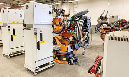
(1) KUKA motor rotor is unbalanced, and the dynamic balance of the motor rotor is defective during manufacturing or becomes worse after use, which will produce a vibration source like "vibration motor".
(2) The bending of the rotating shaft is similar to the imbalance of the rotor. In addition to the vibration source, the coaxiality error of the motor rotor center and the lead screw center will also be generated, causing the mechanical transmission system to jitter.
(3) The coaxiality error of the two parts of the coupling will be caused by the manufacturing defects or wear after use of the coupling. Especially, the casting rigid coupling is more likely to produce coaxiality error and cause vibration due to its poor manufacturing accuracy.
(4) The poor parallelism of the guide rail during manufacturing will cause the KUKA servo system to be unable to reach the specified | position to be unable to stay at the specified | position. At this time, the KUKA servo motor will constantly wander between trying to find the position and the system feedback, making the motor vibrate continuously.
(5) The parallelism error between the lead screw and the guide rail plane, and the parallelism error between the lead screw and the guide rail plane during installation will also cause the motor to vibrate due to uneven load.
(6) When the lead screw is bent, the lead screw will be subject to variable radial force in addition to axial thrust after bending. When the bending is large, the radial force will be large, and when the bending is small, the radial force will also cause vibration of the mechanical transmission system.
2. Electrical
The electrical reason of KUKA AC servo motor is mainly the parameter adjustment of servo driver.
(1) Load inertia. The setting of load inertia is generally related to the size of the load. Excessive load inertia parameters will cause the system to vibrate. The general KUKA AC servo motor can automatically measure the load inertia of the system;
(2) Speed proportional gain: the greater the setting value, the higher the gain, and the greater the system stiffness. The parameter value is determined according to the specific servo driver model and load conditions. Generally, the greater the load inertia, the greater the setting value. When the system does not generate vibration, the greater the setting value is, but the greater the gain, the smaller the deviation, and the easier the vibration is;
(3) Speed integral constant. Generally, the greater the load inertia is, the greater the set value is. The set value should be as small as possible when the system does not generate vibration. However, reducing the integral gain will slow the response of the machine tool and reduce its rigidity;
(4) Position proportional gain: the larger the setting value is, the higher the gain is, and the greater the stiffness is. Under the condition of command pulse at the same frequency, the smaller the position hysteresis is, and too large a value may cause motor vibration;
(5) Acceleration feedback gain: when the motor does not rotate, a small offset will be amplified by the proportional gain of the speed loop, and the speed feedback will generate the corresponding torque, making the motor jitter back and forth.
KUKA AC servo system is superior to stepping motor in many aspects of performance. But in some occasions where the requirements are not high, stepping motor is often used as the executive motor. Therefore, in the design process of the control system, it is necessary to comprehensively consider the control requirements, costs and other factors, and select the appropriate control motor.
Cause Analysis of Touch Deviation of Industrial Robot Teaching pendant
The position touched by the finger does not coincide with the mouse arrow.
Cause 1: After installing the driver, the industrial robot teaching pendant did not vertically touch the bull's-eye center position when correcting the position.
Solution 1: Recalibrate the position.
Phenomenon 2: The touch in some areas is accurate, and the touch in some areas is biased.
Cause 2: A large amount of dust or scale accumulates on the acoustic reflection stripes around the SAW touch screen, which affects the transmission of acoustic signals.
Solution 2: Clean the touch screen. Pay special attention to clean the sound wave reflection stripes on the four sides of the touch screen. When cleaning, the load correction function of the touch screen control card must be carried out with load. There are two types of load correction: "data 'learned' with tools" and "data 'learned' without tools".


